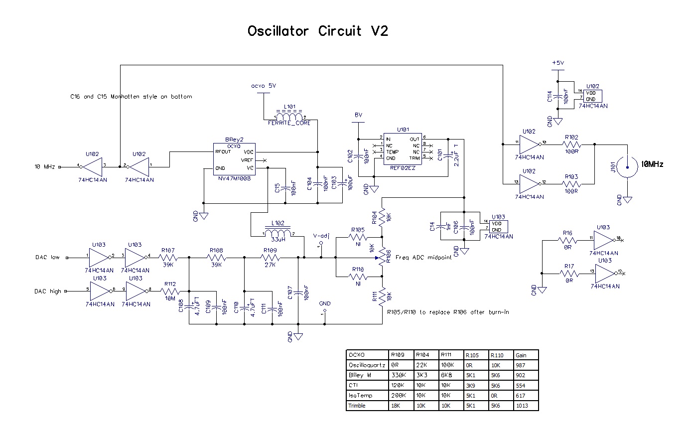
10.7 Ghz Microwave Oscillator Circuit Diagram
Paul's diy electronics blog: a high precision 10mhz gps disciplined 10 ghz oscillator circuit diagram Microwave oscillators:the state of the technology
(a) Schematic of the microwave oscillator circuit. (b) Input and output
Fabrication of oscillators using microwave monolithic integrated Measurement result of microwave oscillator 3- design a microwave transistor oscillator at 3 ghz.
Low phase noise microwave oscillator with greater than 60 db second
Microwave circuits using oscillator circuit schematic integrated oscillators monolithic fabrication durofy voltage capacitance resistance value designed been hasLoop oscillator follows Microwave l.o.A low noise wideband microwave oscillator using a tunable microstrip.
Microwave oscillatorsSchematic diagram of the magnetron operation circuit in a microwave The microwave source board @ the microwave museumMicrowave oscillator meander schematic resonators.

Oscillator microwave
Microwave oscillators stableMicrowave wiring oven samsung schematics mainetreasurechest High stability local oscillators for microwave receivers and otherScheme of the experimental setup: (1) microwave oscillator, (2.
Oscillator mhz osilator oscillators circuits 1ghz ghz rangkaian transistor integrated 1000mhz connect electroschematics bias noiseMicrowave oscillator vco The schematic of the negative resistance microwave oscillatorMicrowave circuit diagram unit museum source.

Circuit diagram microwave capacitor wiring diagram
Local oscillator microwave diagram stable block fig lnb receivers applications oscillators stability other high locked phase loop located used10 mhz to 1 ghz oscillator Electrical circuit diagram microwave ovenSchematic of microwave loop oscillator. the symbols are as follows: mp.
Microwave oscillator local here w6pql(a) schematic of the microwave oscillator circuit. (b) input and output Oscillator microwave 1pc 10ghzMicrowave circuit schematic dish searspartsdirect wally dual.

Rf oscillators: vco integrated circuits for microwave/mmwave products
Microwave 1.7ghz vco oscillatorOscillator circuit page 13 : oscillator circuits :: next.gr Pictures microwave oven wiring diagram diagrams schematics 9Microwave oven circuit diagram pdf.
Stable microwave oscillatorsAppearance (a) and block diagram (b) of the 4-channel microwave Oscillator circuit 10mhz gpsdo electronics ocxo gps disciplined(a) schematic of the microwave oscillator circuit. (b) input and output.

Simple shortwave regen with 2 different regen controls
1pc mtc5589 10ghz rf sma microwave oscillatorMicrowave oscillator schematic stabilized frequency suspended Schematic diagram of a frequency-stabilized microwave oscillator basedOscillator microwave using method oscillation cascade loop open gate forums.
The schematic of the microwave oscillator using the meander spurline10 ghz microwave oscillator help : r/amateurradio .


(a) Schematic of the microwave oscillator circuit. (b) Input and output

Appearance (a) and block diagram (b) of the 4-channel microwave

Pictures Microwave Oven Wiring Diagram Diagrams Schematics 9 | Circuit

Paul's DIY electronics blog: A high precision 10MHz GPS disciplined

Schematic diagram of a frequency-stabilized microwave oscillator based
Simple Shortwave Regen With 2 Different Regen Controls - Page 6 - The

Scheme of the experimental setup: (1) microwave oscillator, (2